Make a Keyboard
Creating a completely custom, handwired keyboard is much more approachable than you would think. Thanks to some great online tools and laser cutting services, you don't need any specialized skills.
 Ross Harmes
All the software used here is free; the only cost comes from the parts (plate, case, switches, keycaps, microcontroller, diodes, wire). Expect to spend around $150 on the low end and upwards of $500 on the high end, though the vast majority of that cost comes from the keycaps (and, to a lesser extent, the switches), so looking on r/mm might net you some deals.
0. Decide on a layout
You can skip this step if you already know what type of keyboard you want to build. If you're looking to build something ergonomic, I highly recommend buying or borrowing keyboards with different features (split, staggered column, ortholinear, thumb clusters, concave, tented, rotated) to find what you like. I started with an Ergodox EZ, which is a fantastic way to test out layouts (since it's so easy to change key assignments via Oryx, and since it has way more keys than you will ever need). The most important discoveries for me were that I have strong opinions about where the thumb clusters are, I really dislike stretching my pinky, and I like having palm rests.
For this guide, I'll be building a new keyboard from scratch—a fixed-split ~60% with staggered rows.
1. Lay the keyboard out using keyboard-layout-editor.com
This is the most important step; everything we do after this step will be based upon the data we generate here. Take your time and make sure you get it right. The purpose of this step is twofold: We will use the positions and sizes of the keys to generate the plate and case, and we will also use the key assignments to kick-start the QMK configuration. You can (and should) save your layouts by logging in with your Github account.
This tool allows you to start with an existing layout, which is a huge time saver. Go to "Preset" at the top and try out the layouts available. If you assign characters to each of the keys, kbfirmware.com will generate an initial keymap for you in step 2.
I started with an Ergodox layout, deleted keys to get down to the ones I wanted, and then changed the key positions and rotations until I was happy with it. I then assigned keys and played around with layers. Since I'm working with a non-standard set of keycaps, I double-checked to make sure I had the sizes I needed for each of the row profiles. Here's my final layout:
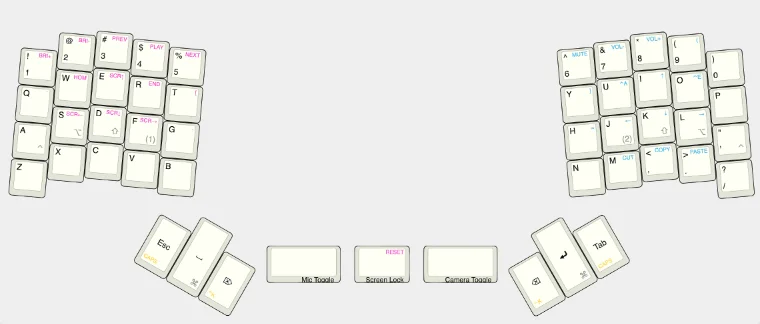
For the next step, you'll need the JSON data for your layout; go to the "Raw data" tab and copy the code there.
2. Generate the wiring diagram and QMK config using kbfirmware.com
Paste your JSON config into the text field and click "Import". You'll probably see a wiring diagram that looks a bit unoptimized, with too many rows and columns used:
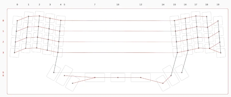
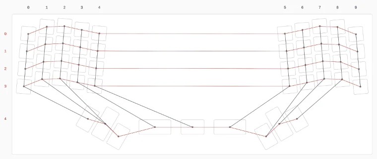
Click on each key and change the row and column numbers until you have a more orderly-looking grid. If you have pins to spare on your microcontroller, then don't try to optimize too much, and instead focus on creating a grid that will be easy to wire up. Once you're happy with it, screenshot this view for later reference. For my layout, the keys at the bottom don't naturally fit into the grid, so I added them as a fifth row, attached to columns to the left and the right:
Next click on the "Pins" tab and assign pins to each of the columns and rows. If you're using an Elite-C, this is easy: Just look at the labels on the board next to each pin and assign the rows and columns however best fits your physical layout. Here's an example of how I laid them out for another board, which used all 23 pins. For our purposes here, all labeled pins are identical, so you can assign them however you like, with the exception of GND, RST, and VCC. Since space is always at a premium inside handwired builds, think about where the wires for each column and row will be coming from and try to assign them to a pin on the correct side of the board. Here's my pin mapping for reference.
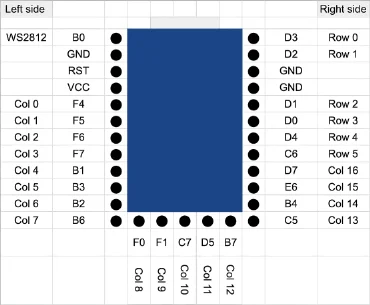
If you're using a Pro Micro, then you'll have to do some translation for the pin labels. The GOLEM Keyboard Project has a mapping that I found really helpful. Since I'll be using an Elite-C, I put the rows down one side and the columns down the other, while also assigning a pin to a WS2812 RGB LED to use for indicating layer.
The last step for the firmware builder is to ensure we have the keys assigned properly. We'll be editing these later, so they don't have to be perfect, but assigning keys here means you have a head start later. This is the starting keymap that I used:
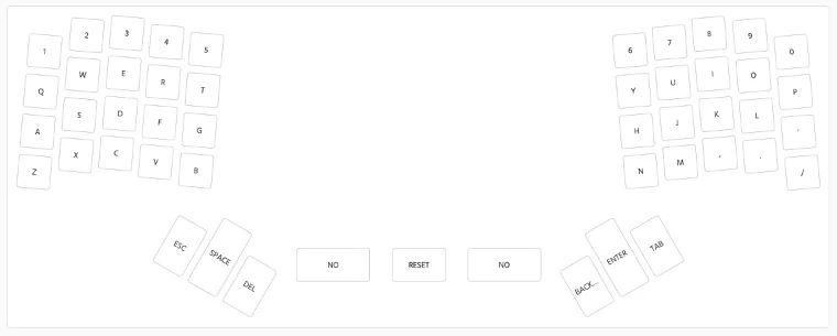
⚠️ This site doesn't save any of the work you've done automatically; you'll have to go to "Settings" and click "Save Configuration" to download a JSON file. You can come back to this site and load that JSON file any time you want to make changes. Once you're done making changes, go to "Compile" and click "Download .zip" to download the firmware code, and click "Download .hex" to download the compiled firmware; we'll dig into these files in step 7.
3. Generate the vector files for the plate and case using builder.swillkb.com
Using the same JSON config from step 1, go to builder.swillkb.com and paste the JSON into the "Plate Layout" field. Select your switch type (probably MX) and your stabilizer type (probably Cherry), decide if you want edge padding or rounded corners, and then click "Draw My CAD!!!". You'll see something like this:
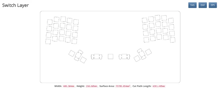
Click "SVG" in the upper right to download the svg file, which we'll edit in the next step.
4. Edit the vector files using Inkscape
We'll be using the switch positions from builder.swillkb.com and using Inkscape to form the outline of the case and add holes for stand-offs. After you download and install Inkscape, use it to open the svg file from step 3. If you're on a Mac and it's running slow for you, try this tip (which worked for me): Select the Inkscape app in the Finder and Get Info. then select the "Use low resolution" checkbox.
I've found that the easiest way to form complex shape is to start with basic shapes (circles and rectangles) and use them to add and subtract from other shapes using the Union and Difference commands. Inkscape has a great beginners' guide which can help explain how to create and manipulate basic shapes. For this step, you'll want to:
- Ensure there is an outer shape for the plate, which will be the middle layer in our sandwich. I used a simple rounded rectangle.
- Add holes for the standoff. You'll want 3mm holes for the small screws and 6mm holes for the hexagonal part. I added small holes to the base and top, and large holes to the other layers.
- Add cutouts for anything else that will need to poke through the plate. I added 3mm wide rectangles for the pin headers of the RGB LEDs to protrude through, as well as the pin headers of the Elite-C.
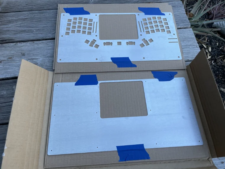
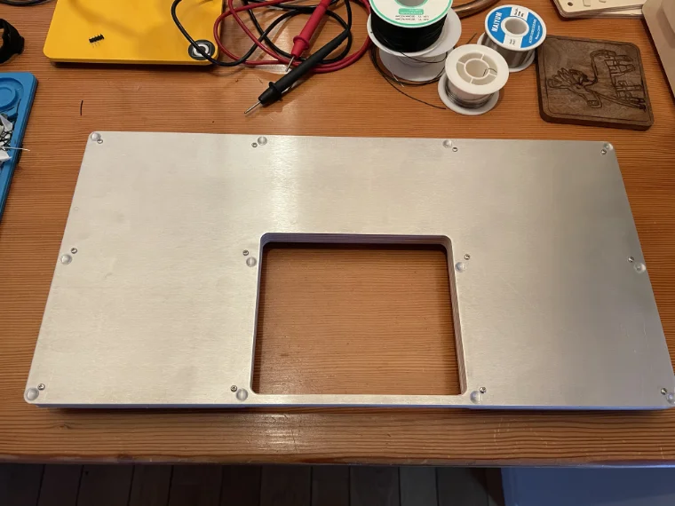
Once you have all the features in place, make a copy of the file and remove everything except for the small holes for the base layer. Here are the svgs for my plate and base layers (the large rectangular cut-out in the middle is just for aesthetics right now, but long-term I want to build something to put here):
5. Order the plate from a laser cutting service
Now that we have the plate and base designed, we can send the svg files to a laser cutting service. I'm using a company local to me, Ponoko, but there are a huge number of local and online services, so search around. Regardless of service, these are the steps to ensure your parts are the correct size:
- Upload the svg: Select the plate or base svg file and upload it.
- Select the material: Aluminum and steel both work well. Ensure the thickness is 1.5mm or less, otherwise the switches won't seat properly.
- Confirm the size: Using the dimensions from Inkscape, enter the height and width.
I went with 1.0mm aluminum (Ponoko does't offer 1.5mm, and I worried that 1.6mm would be too thick for the switches to seat properly). Here's the cost for these two parts:
| Base | Standard Aluminum, 419.1mm x 208.6mm x 1.0mm | $18.81 |
| Plate | Standard Aluminum, 419.1mm x 208.6mm x 1.0mm | $34.72 |
| Order setup | A once-per-order labor cost | $14.00 |
| Multi-item discount | -$7.66 | |
| Total | $59.87 |
You can build a keyboard with just the plate and bottom, with standoffs separating them, but most builders prefer to have a layer in between them and another on top. You can create these in the same way as the metal parts above, and have them lasercut in acrylic or wood. I'm fortunate enough to have a small CNC router in my workshop, so I'll be using that to cut the remaining case pieces out of 3mm and 6mm Baltic Birch plywood. Note that you will need to use small holes in your plate layer, for screws, if you aren't using other layers; since my plate will just be another layer in the sandwich, I'm using large holes, for the standoffs.
6. Order the rest of your parts and tools
This is a great time to order the rest of the parts you'll need to assemble the keyboard. The specifics will vary for you, but this is the list I used for my build (keep in mind that many of these give you extra, so your next build will be cheaper):
| Part | Model | Quantity | Total cost | Source |
|---|---|---|---|---|
| Switches | Gateron Silent Ink v2 | 50 | $42.50 | NovelKeys |
| Microcontroller | Elite-C v4 | 1 | $17.99 | keeb.io |
| Diodes | 1N4148 Through-Hole | 100 | $2.71 | Digi-Key |
| RGB LEDs | WS2812B (optional) | 6 | $17.88 | Digi-Key |
| Standoffs & screws | M2.5 Kit (can also be ordered individually from McMaster-Carr if you know what you need) | 1 | $16.95 | Digi-Key |
| Rubber bumpers | 3M Bumpon pack (96) | 1 | $9.94 | Digi-Key |
| Wire | Wire Wrap 30 AWG Solid Core | 1 | $13.40 | Digi-Key |
| Solder | Rosin Core (optional; some will come with the soldering iron) | 1 | $24.95 | Digi-Key |
| USB-C cable kit | 4 ft. (optional if you have one already) | 1 | $9.35 | Zap Cables |
In addition, you'll need some tools. Few are strictly required—as long as you have some way of soldering, you're fine—but many will make the job significantly easier. Below are the tools I used, and how useful or optional I found each to be. One note: You can find most of these cheaper if you search around. I believe that good tools are an investment, but you can find models of all of these tools for a quarter of the price or less. We'll start with the required tools:
| Tool | Model I use | Usefulness | Total cost | Source |
|---|---|---|---|---|
| Soldering iron | Dremel Versatip | Required; use a plug-in model if you're a beginner. | $49.99 | Digi-Key |
| Tip cleaner | Hakko 599B | Required, but one should come with the soldering iron. You can also use a wet sponge. | $13.26 | Digi-Key |
| Wire stripper | Jonard Tools ST-500 | Required, but there are very cheap models out there that work, and a wire wrap tool will have one built-in. You can even use a razor blade. This model is a fancy one specifically for the the diameter of wire we're using, and is the best I've found. | $41.50 | Digi-Key |
| Side cutter | NWS Side Cutter | Required to cut wire and trim the ends of diodes. | $29.86 | KC Tool |
| Multimeter or continuity tester | Fluke 179 | Required to test continuity once the board is wired up, but you can make your own. High-quality models can be found used on eBay, which is what I did. | ~$100.00 | eBay |
| Screwdriver | Small Philips | Required; can be any small Philips you have lying around. | $0.00 |
Next are the tools that are optional, but helpful:
| Tool | Model I use | Usefulness | Total cost | Source |
|---|---|---|---|---|
| Wire wrap tool | Vectech CB-30M or Jonard Tools WSU-30M | Optional, but wire wrapping is a clean and reversible way to wire up your board. Any model that can handle 30 AWG wire will work. | $58.08 | Digi-Key |
| Pliers | NWS Chain Nose Pliers | Optional, but incredibly useful in bending diodes and placing components. | $26.56 | KC Tool |
| Silicon mat | Sparkfun TOL-14672 | Optional; helps protect both your work surface and your parts. | $15.39 | Digi-Key |
7. Finalize the firmware with QMK
While we're waiting on our parts to arrive, we can focus on the firmware. First you have a decision to make: Do you want to use this firmware as-is, using the keymap you defined in step 3, or would you like to add layers and other advanced features? If you want to go the more advanced route, you will need to be comfortable editing text files and running commands on the command line. We'll start with the more straight-forward approach:
Option A. Using the firmware as-is
First you'll need to download the QMK Toolbox app. Next, find the hex file that you downloaded at the end of step 3. That's it! You have everything to need to flash the microcontroller later, in step 9.
⚠️ If you ever want to modify this keymap, you'll need the JSON file from step 3, so be sure to hold onto that. You can then load that file into kbfirmware.com, change the keymap, and download new hex and JSON files.
Option B. Modify the firmware to add features
This is the most durable and maintainable approach, and at the end of it, you will be comfortable working with QMK. While most of the files that you'll be editing are written in C, you don't have to be familiar with C; this is more akin to modifying config files than it is to programming in C. The QMK docs are really good, and explain the setup better than I can. Here is the order I would use when setting it up:
-
Fork the
qmk_firmwarerepo - Prepare your build environment and run QMK setup
-
Configure your upstream and
create a
devbranch
Now that you have QMK forked and working, we can
move on to setting up your firmware. For the
rest of this step, you'll need to have a name
for your keyboard. I'm using am49,
so when you see that below, replace it with your
name. From within the top level of the
qmk_firmware repo, create an empty
directory with the name of your keyboard:
cd keyboards/handwired
mkdir am49
At the end of step 3, you downloaded a zip file;
open that up now and you'll see a directory
named qmk_firmware. Within that
directory, navigate to
keyboards →
kb and move all the files there to
the directory you created above. Rename
kb.c and kb.h to the
name of the keyboard.
cd am49
mv ~/Downloads/qmk_firmware/keyboards/kb/* .
mv kb.c am49.c
mv kb.h am49.h
Only two changes are required to the files themselves:
-
Open
am49.candkeymaps/default/keymap.cand replace#include "kb.h"with#include "am49.h". -
Open
keymaps/default/keymap.cand delete every line fromconst macro_t *action_get_macro(keyrecord_t *record, uint8_t id, uint8_t opt) {to the end of the file.
You can now compile your firmware to make sure everything works:
qmk compile -kb handwired/am49 -km default
If everything went well, you'll see a lot of
lines ending with [OK], followed by
something like this:
Linking: .build/handwired_am49_default.elf                              [OK]
Creating load file for flashing: .build/handwired_am49_default.hex      [OK]
Copying handwired_am49_default.hex to qmk_firmware folder               [OK]
Checking file size of handwired_am49_default.hex                        [OK]
 * The firmware size is fine - 23324/28672 (81%, 5348 bytes free)
You now have a working base that you can modify as much as you like. I recommend committing and pushing back to your fork at this point, before you get too deep into modifications. A good first change would be to play around with keycodes and layers, then move from there to Mod-Tap and Combos. You can also look around at other handwired boards for inspiration; am49 and am96 are two that I've built.
8. Flash the microcontroller
You can complete this step before or after assembly, as long as you have the microcontroller in front of you; I prefer to do it before. Plug the microcontroller into your computer now.
Option A. Flash using QMK Toolbox
Go with this option if you also went with option A in step 7. Open QMK Toolbox, select your hex file, reset your microcontroller (there is a small button on the Elite-C for this; other microcontrollers may have you bridge two pins to reset), and click "Flash". For more details, check out QMK's flashing instructions.
Option B. Flash using the command line
Go with this option if you also went with option
B in step 7. After you've compiled your
firmware, you can flash the microcontroller with
this command in the Terminal (again, replace
am49 with the name of your
keyboard).
qmk flash -kb handwired/am49 -km defaultIf you encounter any errors, check out the bottom half of QMK's flashing instructions.
9. Assemble
Once you have all your parts and tools, you can begin assembly. This is the most time-consuming step, but is relatively straight-forward; most of the complexity is behind us. We'll be soldering and wire wrapping to connect the switches together; if you're new to either, here's an in-depth soldering tutorial and a quick wire wrapping tutorial. You can also just solder if you'd prefer not to wire wrap.
A. Inspect the plate
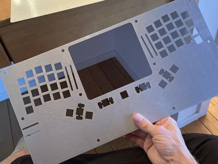
Unpack the plate and the case bottom and check that it matches your design. I like to take calipers and measure the switch cutouts and holes to make sure everything is as expected; this is the best time to find any errors (not after you've started soldering your switches). Run a piece of sandpaper over the edges to smooth over any sharp parts.
B. Prep your work area
Gather all your tools and parts and double check that you have everything you need. There is nothing worse than finding mid-way that you're short a few parts or that you can't find a component you need.
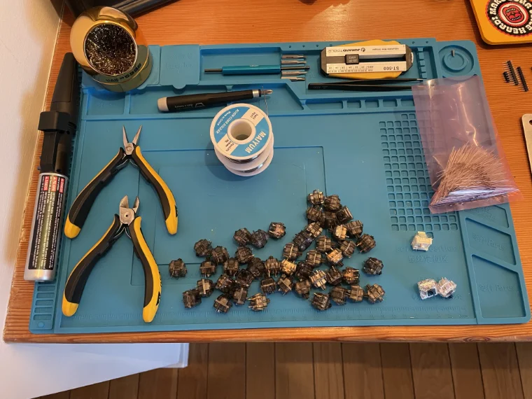
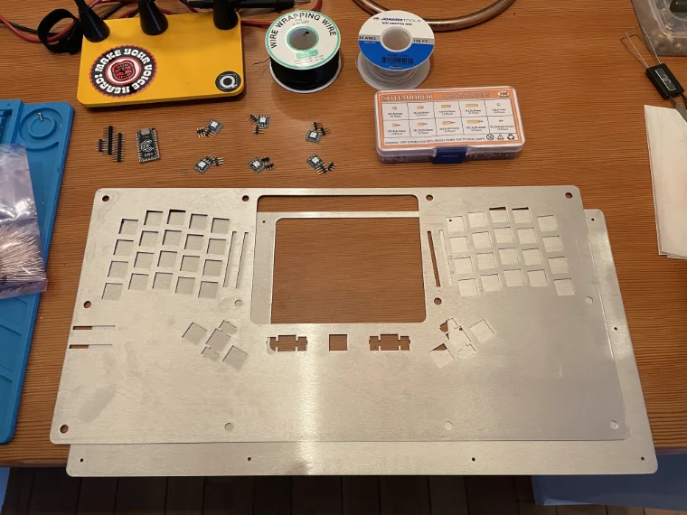
C. Test fit the switches and keycaps
Before we start wiring, we want to make sure all the switches fit, and that the keycaps don't rub. Insert the switches into the plate, add the keycaps, and then assemble the rest of the case around it. Ensure the keys don't touch each other or the case, that there is enough room between the plate and the bottom of the case, and that the holes in each layer are correctly sized for the standoffs and screws. In my case, everything fit, but the smallest holes were too small for the screws, so I had to drill those out later.
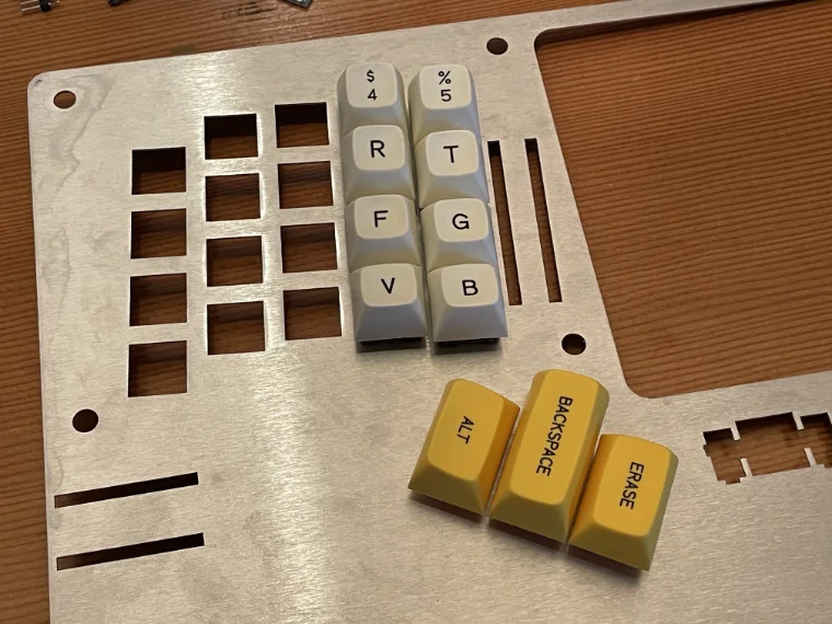
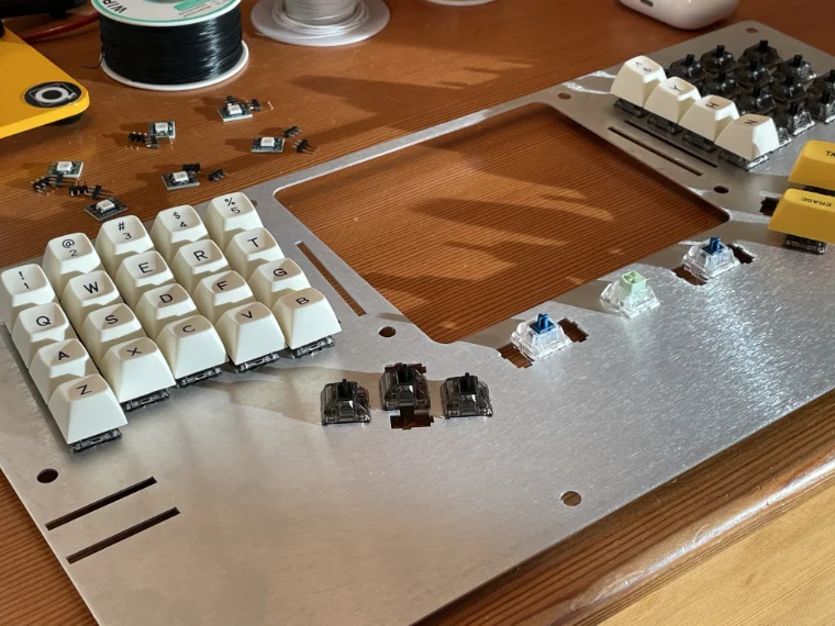
D. Bend the diodes and solder them in place to form the rows
We're now ready to start soldering. We'll first connect all the rows together using diodes. A few things to keep in mind:
- Orient the diode such that the black band is facing away from the pin.
- Connect all the switches in the row together after the diode, not in between the diode and the switch.
- You can connect the row to the microcontroller from any point after the diode.
- You can connect either switch pin to the row or the column. I usually connect the left pin to the row and the right to the column.
- Before you solder, make sure your work area is well-ventilated. Use a fume extractor if you have one, or open windows and use a fan to direct the soldering fumes outside.
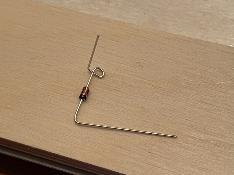
Take a diode and bend it to match the shape in the photo below. You want a loop that fits over the switch pin (this is the part we'll be soldering) and a 90° bend which we'll use to connect it to the next switch in the row. I place the diodes from right to left, working one column at a time (this allows the 90° bend from the next diodes to rest on the already soldered ones).
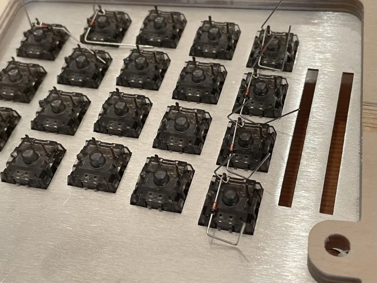
⚠️ Make sure you orient the diodes with the black band facing away from the pin; check the photos here to see the correct orientation. I got this wrong the first time, and had to unsolder all the diodes and start again.
Once you have an entire column in place, solder the diodes to the pins and trim the excess wire with your side cutters. Ensure that no part of the wire is touching the plate, since it's conductive. This is what it should look like; since this is the end of the row, I've left vertical tails that we'll use to wire wrap later, but the other diodes won't have this.
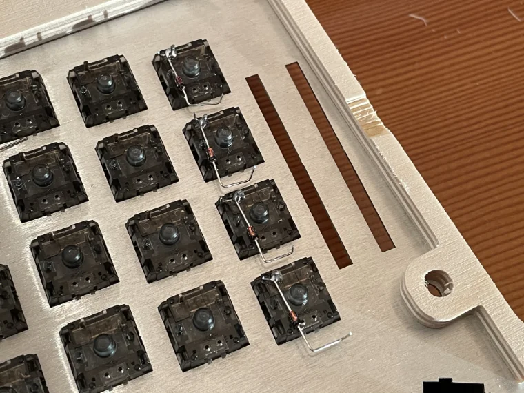
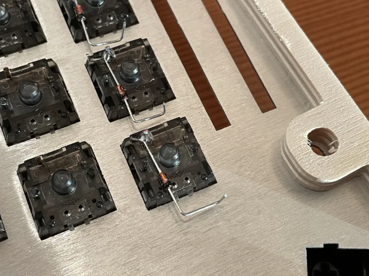
Move on to the next row, overlapping the 90° bend. When they're all in place, solder both the loop to the pin and the tail to the previous diode. Move across the board like this until the rows are all connected together.
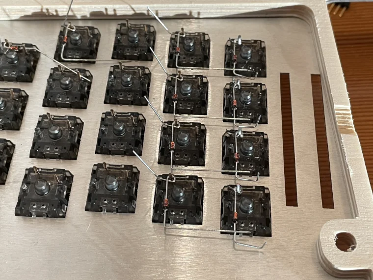
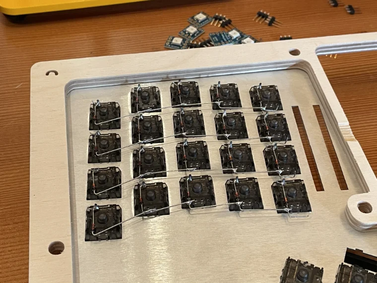
If your layout is a fixed split like mine, you'll have the bridge the gap between the halves. I wire-wrapped from one side to the other, ensuring the rows are connected after the diodes. Then connect each row to the pin you defined for that row in step 2.
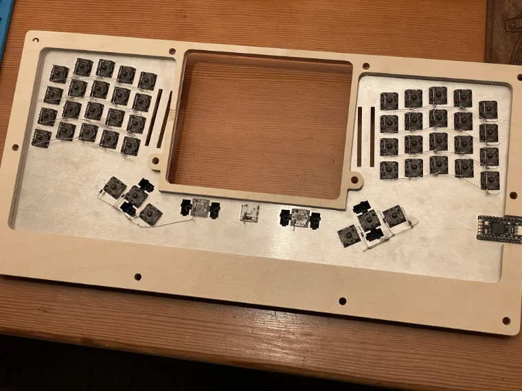
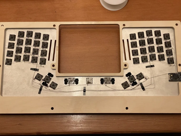
You're all done with the rows! Use your multimeter or continuity tester to check for continuity; touch a probe to the farthest end (after the diode) and another to the microcontroller pin, and make sure you hear the tone (here is a quick guide for testing continuity). Also touch adjacent rows and ensure they are not connected.
E. Wire wrap to form the columns
The columns are less complex than the rows; with no diodes to worry about, it's just a matter of connecting all the switch pins to the right pin on the microcontroller. To do this, we'll wire wrap one switch pin to the next, and then connect the bottom one to the Elite-C. In the photos below, the columns use black white, while the rows use white wire and bare wire. Since the gaps between switches are the same in the columns (I'm using columnar stagger), we can save a lot of time by creating the pieces of wire in batches.

Below on the left, you can see two columns wired together, one pin to the next. In the photo on the right, the entire right side is done and wired back to the microcontroller. It's up to you if you want to solder the wire-wrapped connection (I did).
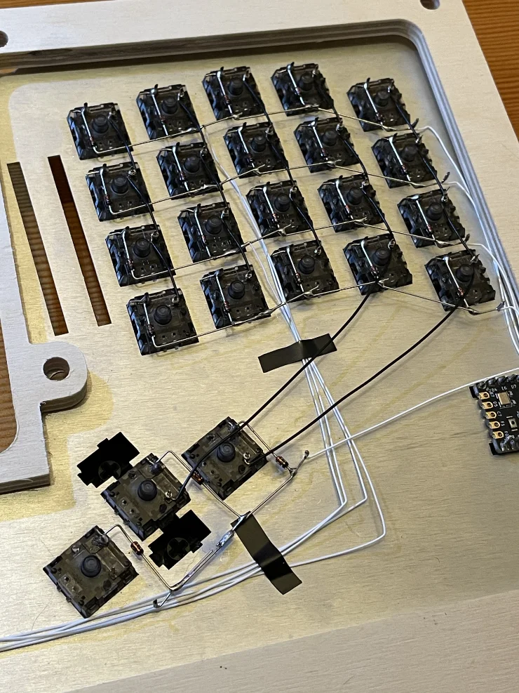
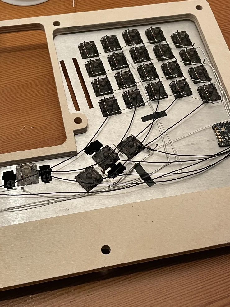
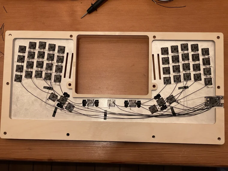
The columns are complete! Like with the rows, use your multimeter or continuity tester to check for continuity, from the farthest switch pin to the microcontroller pin. Also touch adjacent columns and ensure they are not connected (though there is less of a risk of that here, since we don't have any bare wire like with the diodes).
F. Assemble the case with standoffs and screws
Last step in the assembly: We put the sandwich case together using M2.5 standoffs and screws. Since my case bottom is conductive, I covered the possible contact points on the inside with electrical tape and stickers. If there is enough room where there is no danger of touching, then you can skip this step. Line everything up and ensure your holes all match across the layers.
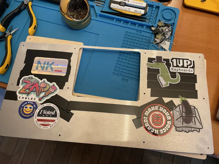
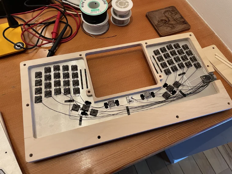
Using the assortment of M2.5 standoffs, try a few different heights and see which one allows screws to reach from both the top and the bottom. In my case, I'm using two different heights, since the bottom four will have an extra 9mm of height for the palm rests. Then start driving the screws from the top.
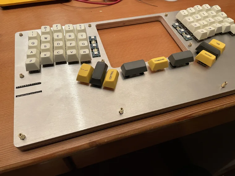
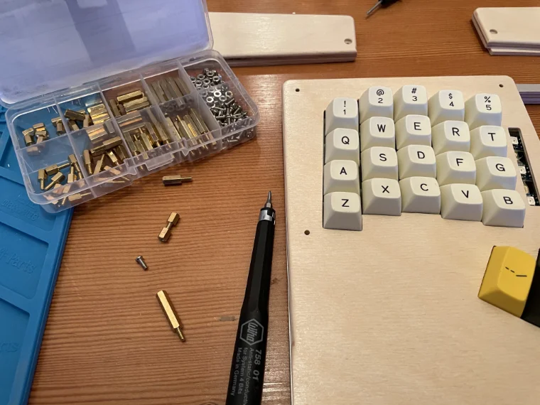
Flip it over and drive the screws from the back. You have to keep everything aligned during this step, and you may need to re-tighten the screws on the top afterwards. Add rubber feet to keep the keyboard from moving around your desk.
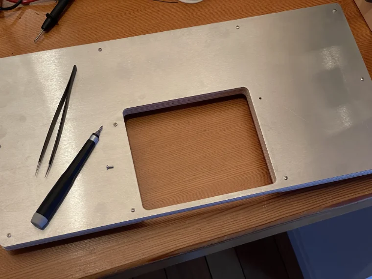
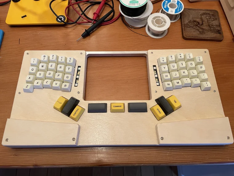
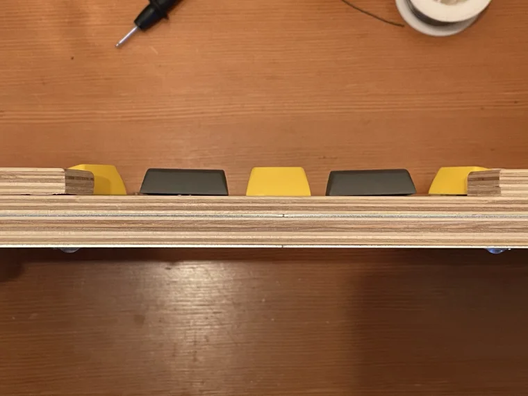
The keyboard is now fully assembled. Here's the final view from the top and the sides. On the side view, you can see the layers (from the bottom: 1mm aluminum, 9mm plywood, 1mm aluminum, 6mm plywood).
10. Test and debug
Plug your keyboard in and open keyboardtester.com; press each key to ensure it works. If you have layers, check each key on those layers as well. If everything works, great! If not, it could be a problem with your keymap or with your wiring. If a part of a row or column doesn't work, it's probably a loose connection that needs to checked. If incorrect characters are being entered when you press keys, then it's probably your keymap (either the layer, the layout, or the keycode; check all three).
If you keep encountering problems, take the case bottom off and ensure that all diodes have the black band facing away from the switch pin, and that all switches are connected to a row and column. Pull out your multimeter or continuity tester and ensure that each column is connected from the farthest switch pin to the pin on the microcontroller, and that each row is connected (on the non-switch side of each diode) in the same way. If you have concerns about any of the switches themselves, you can test them by touching your leads to each pin and pressing the switch; if it's working properly, the continuity tester will sound.
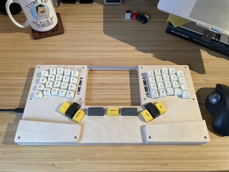
I'm quite happy with how mine turned out. The keys are in just the right places, and the palm rests keep my wrists at a neutral angle (I tried out three different heights to see which I preferred). Here it is plugged in on my desk; I typed up all these instructions on this keyboard.
You've created a custom keyboard; congrats! You may find that it takes a week or two to get used to the layout. Practicing for 15 minutes a day will speed up the transition. Focus on accuracy over speed; once you're confidently hitting the correct keys, speed will come naturally. Happy clacking!
Acknowledgements
While this guide was written from scratch, the fact that I know how to make a keyboard at all is thanks to the hand-wiring guide in the QMK docs, matt3o’s BrownFox Build Guide, and Masterzen's Handwired Keyboard Build Log. They're great; do yourself a favor and check them out.
Thanks to all the people who tirelessly maintain the tools that allow us to build keyboards like this. We stand on the shoulders of giants, and this guide would not be possible without keyboard-layout-editor.com, kbfirmware.com, builder.swillkb.com, Inkscape, and, most especially, QMK.
Feedback or corrections
If you have any thoughts, edits, or suggestions, please email me. Put "makeakeyboard.com" in the subject so that I see it 🙇♂️